Our funding comes from our readers, and we may earn a commission if you make a purchase through the links on our website.
Port Mirroring – A Definition & How It Works (Tutorial) & LAB!
UPDATED: March 21, 2023
One of the most useful techniques available to network engineers is Packet Capturing, but in order to do this, We'll need to dig into How to do it using a popular Technique called Port Mirroring.
By looking into the packets as they are sent across a network, a couple of interesting things become possible including deep troubleshooting of network issues, security monitoring and investigation, and also the ability to learn about various technologies.
However, Packet Capturing can be challenging on a switched network and we will discuss why in this article. We will then consider a way to make packets meant for one segment of a network to “appear” on another part of the network, aiding in effective capturing of packets.
Switches vs Hubs
If you have been in the networking industry even for a bit, then you have probably heard of the difference(s) between a hub and a switch. Relevant to our discussion is the fact that when a hub receives a packet, it forwards that packet to all ports on that hub (except the port on which the packet was received), whether that packet is destined to the devices connected to those ports or not.
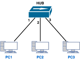
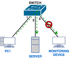
For example, if PC1 wants to send a packet to PC2, the hub will forward that packet out both ports 2 and 3, even though PC3 has no business with that packet.
We can easily see this by looking at a simple lab in GNS3:
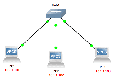
If I ping from PC1 to PC2 while capturing on the link between the hub and PC3, I will see those ping packets also being sent out to PC3 (even though that device will ignore them as they are not addressed to it):

On the other hand, a switch is an intelligent device that is able to forward packets only to the port on which the destination device belongs. To do this, a switch keeps a MAC address table that matches MAC addresses to the ports on which those addresses appear. So when a switch receives a (unicast) packet, it will go through the following steps:
- Check its MAC address table for the MAC address of the destination.
- If the MAC address is found in the table, the switch will forward the packet out only on the interface associated with that MAC address in its table.
- If the MAC address is not in the table, the switch will flood the packet out all interfaces except the interface on which the packet was received. Assuming the packet is part of a ‘string’ of other packets, the switch will eventually learn the port on which the destination device is and start sending packets out only on that interface.
To confirm this behavior of a switch, we can also do the same test we did in the case of the hub; however, we will change the hub to a switch.
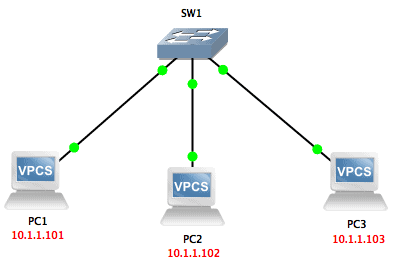
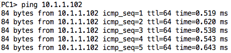
We will ping from PC1 to PC2 again while capturing packets off the link between SW1 and PC3:

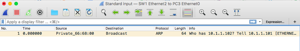
As you can see, the only packet received by PC3 was the ARP request sent by PC1 trying to resolve the IP address of PC2. Once the switch learned the port on which PC2 belongs, it did not forward packets destined to PC2 to its other ports.
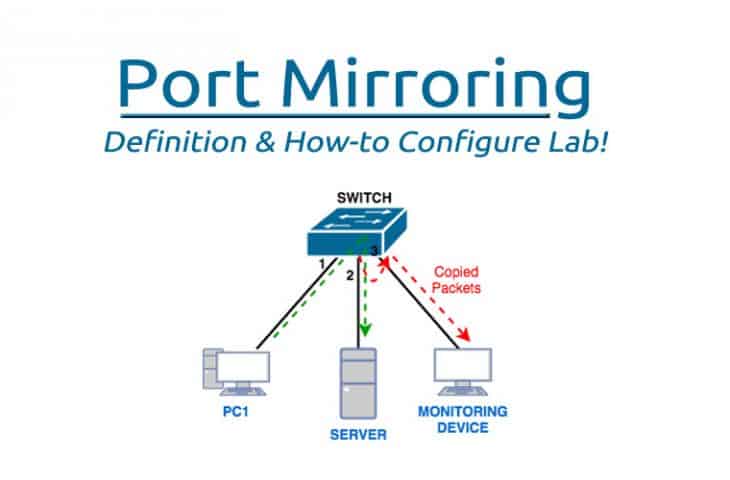
Packet/Port Mirroring
Why did we go through the trouble of explaining the difference between switches and hubs? Well, we did so because most networks today are switched networks which can be a challenge for packet capturing.
As we highlighted at the beginning of this article, there are several reasons why you will want to capture packets including troubleshooting network issues, investigating security incidents, and also for learning purposes. However, since switches do not flood packets out all ports, how will a device used for capturing packets receive packets that are destined to other devices on the network?
This is where Port Mirroring comes into play.
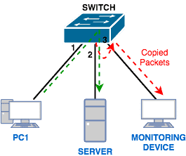
Basically, with Port Mirroring, packets sent/received on a port/VLAN are copied to another port. This feature is available on many switch models including Cisco, Juniper, Netgear, and so on. Also, it is known by different names apart from Port Mirroring depending on what vendor you are dealing with.
For example, on Cisco switches, this feature is known as Switched Port Analyzer (SPAN).
Focus: Cisco SPAN
Let us now get practical and see how Port Mirroring works in reality. To do that, we will focus on Cisco’s implementation of port mirroring, known as SPAN. Let us first get some common terms out of the way:
- Source port/VLAN:
This is the port/VLAN that is being monitored. Traffic on ports/VLANs can be monitored ingress (coming in), egress (going out), or in both directions. - Destination Port:
This is the port to which the traffic from the source ports/VLANs are sent/copied to. In most cases, this is where you will connect a traffic analyzer like Wireshark. - SPAN Session:
This is the combination of source ports/VLANs and destination ports. Each SPAN session can contain multiple source ports/VLANs and multiple destination ports (up to a certain maximum depending on hardware).
Cisco also offers three major types of SPAN including:
- Local SPAN:
In this case, all the source ports/VLANs and the destination ports are on the same switch (or switch stack). - Remote SPAN (RSPAN):
In the case of RSPAN, the monitored ports/VLANs and destination ports are distributed among several switches. A good example of when this is necessary is in a data center. Imagine that you want to capture traffic from a server switch rack where all the ports on the switch are occupied meaning there is no free port to which to connect the traffic analyzer.What you can do is to configure RSPAN between that server switch and another switch that has free ports, and then connect your traffic analyzer to that switch with free ports. - Encapsulated Remote SPAN (ERSPAN):
This is similar to RSPAN except that the mirroring goes beyond layer 2 to layer 3 – GRE is used to encapsulate the SPAN traffic between switches separated by a routing domain.
There are various guidelines and restrictions for the source ports/VLANs and destination ports for the different SPAN types and you can read about them here. For example, a destination port cannot also be a source port. Also, in a particular SPAN session, you can either monitor ports or monitor VLANs; you can’t mix both.
Lab: Local SPAN
Let’s look at a Local SPAN lab using GNS3. The lab setup is as shown below:
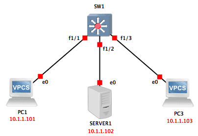
GNS3 does not support switching capabilities by default. However, we can add a switch module (NM-16ESW) into a router to get some switching features. I also changed the symbol of the router to look like a multi-layer switch.
Finally, I changed the symbol of one of the PCs to look like a server.
In this lab, we will assume PC3 is the device we want to use for monitoring and we want to monitor all traffic going to/from the server. This means that our source port is Fa1/2 while our destination port is Fa1/3.
To achieve this, the configuration on our switch (done in global configuration mode) will be as follows :
no monitor session 1

monitor session 1 source interface Fa1/2

monitor session 1 destination interface Fa1/3
The first command (no monitor session 1) removes any previous SPAN session 1. This is just to be on the safe side because if there is an existing SPAN session and you configure anything extra on that same session, it will not overwrite the existing session but update it.
The second command configures Fa1/2 as a source port. Notice that the output does not show if its ingress (rx) or egress (tx). This is because the default is both directions.
Finally, the last command configures Fa1/3 as a destination port.
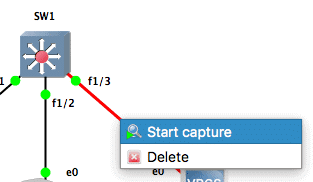
Let us enable packet capturing on the link between PC3 and the switch. Ideally, in a real scenario, you will connect a computer running a traffic analyzer (such as Wireshark) and start capturing traffic off the interface connected to the destination port.
For the interface to capture traffic destined to other devices, it must also operate in promiscuous mode.
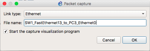
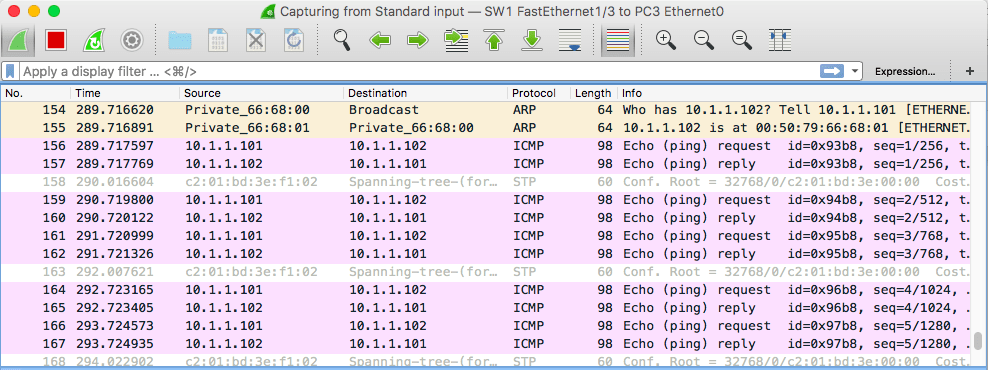
This should open Wireshark and you should start seeing some random packets, mostly related to STP. To see if our configuration is working, let us ping from PC1 to SERVER1. The ping packets should be copied to Fa1/3 and show up in our Wireshark interface:
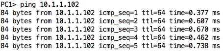
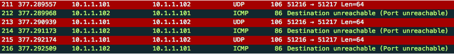
It works! We can also try a traceroute from PC1 to SERVER1.

We will also see those packets pop up in Wireshark:
To show you that we can monitor several source ports, let us edit our configuration to also monitor traffic ingress Fa1/1. This means there will be some redundant packets but that’s okay for our test scenario. To achieve this, just add the following:
monitor session 1 source interface Fa1/1 rx
If you were to check the configuration, you will notice that the SPAN session has been updated:
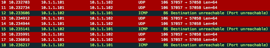
Performing the traceroute again, you will notice there are now duplicate packets (at least one way):
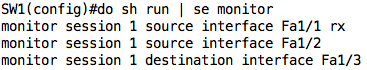
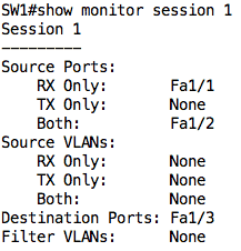
On the switch, we can also issue the show monitor session <num> command to see our SPAN session configuration:
You can learn how to configure the other SPAN types here, although you will probably need to use real switching gear, as GNS3 or Packet Tracer may not work.
Challenges with Port Mirroring
While Port mirroring usually does not result in any performance impact on the Switch itself, one needs to be careful not to overload the destination port. For example, if you are monitoring traffic on several source ports and using only one destination port, the traffic going out that destination port may overwhelm the port resulting in dropped and lost packets.
Another challenge that is indirectly related to Port Mirroring is where to store the packets being captured. If you are capturing packets off a mirrored port, especially in a large network, the data can grow large very quickly and you will need to factor in where to store that data.
Conclusion
This brings us to the end of this article where we have seen how Port Mirroring can be useful in switched networks. We focused on Cisco’s implementation of Port Mirroring, Switched Port Analyzer (SPAN), and then looked at a lab of Local SPAN in GNS3.
Port Mirroring FAQs
What is the purpose of Port Mirroring?
The purpose of Port Mirroring is to provide network administrators with a way to monitor network traffic, troubleshoot network issues, and perform security assessments.
What are the types of Port Mirroring?
The two types of Port Mirroring are Switch-based Port Mirroring and Router-based Port Mirroring.
What is Switch-based Port Mirroring?
Switch-based Port Mirroring is a type of Port Mirroring that is performed on a switch and involves copying packets from one or more switch ports to a designated monitoring port for analysis.
What is Router-based Port Mirroring?
Router-based Port Mirroring is a type of Port Mirroring that is performed on a router and involves copying packets from one or more router interfaces to a designated monitoring interface for analysis.
How does Port Mirroring work?
Port Mirroring works by copying or duplicating packets from one or more switch or router ports to a designated monitoring port or interface. The copied packets can then be analyzed using network monitoring tools such as packet sniffers or network analyzers.
What are the benefits of Port Mirroring?
The benefits of Port Mirroring include improved network visibility, troubleshooting, and security. By monitoring network traffic, administrators can identify network problems and resolve them quickly, improve network performance, and detect security threats.
What are the limitations of Port Mirroring?
The limitations of Port Mirroring include increased network traffic and reduced network performance. Monitoring network traffic can generate a significant amount of traffic, which can put additional strain on the network. Additionally, duplicating packets can consume network resources and reduce network performance.
Can Port Mirroring be used to monitor encrypted network traffic?
No, Port Mirroring cannot be used to monitor encrypted network traffic, as encryption makes the network traffic unreadable to most network monitoring tools.
What are the best practices for Port Mirroring?
The best practices for Port Mirroring include using dedicated monitoring ports, using VLANs to isolate monitoring traffic, and configuring monitoring tools to minimize network impact. It is also important to ensure that Port Mirroring is performed in accordance with applicable laws and regulations.
Related Post: Best Pop Up and Adblockers