Our funding comes from our readers, and we may earn a commission if you make a purchase through the links on our website.
Tagged, UnTagged and Native VLANS Tutorial – A Quick Guide about What they Are?
UPDATED: December 12, 2023
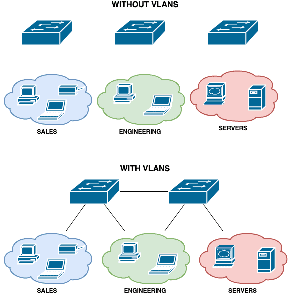
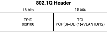
In the early days of networks, we used hubs to connect devices to a local area network (LAN). These devices were unintelligent – they forwarded every packet they received to every other device connected to them resulting in a very “noisy” network.
They also had a single broadcast domain meaning that all broadcast traffic was sent to all devices connected to them. Moreover, all the ports on a hub (of those days) were also in a single collision domain which meant that if two devices tried to talk on the network at the same time, their packets would collide and they would need to resend those packets.
As networks evolved, network devices got smarter and we saw the advent of switches.
Each port on a switch was in its collision domain which means that multiple devices connected to a switch can send packets at the same time. Also, switches could keep track of the port to which devices were connected.
This means that switches do not need to flood packets out of all ports except to the port on which a device is connected.
Note: Flooding still occurs for broadcast packets and also for unicast packets for which the switch does not know about the destination MAC address.
However, switches were still limited to a single broadcast domain which means that broadcast packets are sent to all ports on that switch.
It also meant that segmentation was on a per-device basis: if you wanted to differentiate between sets of users on the network, you need to connect them to different switches.
While this is not a big deal on smaller networks, it is clearly inefficient on larger networks. Enter the world of VLANs.
Note: Throughout this article, the words “packet” and “frame” are used interchangeably even though from a technical point of view, they mean different things.
What is VLAN and How it Works
A logical division of devices on a physical network is known as a virtual local area network (VLAN). Devices are organized into groups and given unique network IDs that are distinct from those used by the rest of the network.
Without taking into account the inadequacies of the Ethernet, VLANs would not have been created as they are today. The Ethernet was a novelty in the 1970s since connecting numerous devices together had never been done before. However, it encountered many issues during that period.
In fact, the first routers and switches were created to solve the problem of garbled signals caused by multiple devices transmitting broadcasts simultaneously. But, it also failed to address the issue of constant broadcast traffic. Later. network professionals figured out that as the number of devices were increasing the efficacy of their networks would decline.
However, as businesses started allowing more and more workers to work remotely, LANs became impossible to maintain, eventually giving rise to virtual area networks.
As said before, VLANs function by logically dividing a large network into numerous smaller networks. Broadcasts can be sent and received by linked devices on each VLAN, which is an independent network. But keep in mind that configuring a VLAN can be challenging.
Sometimes global broadcasts or communication between VLANs are required by businesses.
For example, a scanner or smart TV on one VLAN should be accessible to a computer on another. At the same time, perhaps it would be inappropriate for members of the customer success team (using their own VLAN) to communicate with systems on the financial team VLAN.
The use of access ports for communication between subnetworks is governed by VLANs. The access port determines whether to pass the VLAN data through when a broadcast or frame reaches a switch.
Virtual Local Area Network (VLAN)
A VLAN is a logical grouping of devices on a network with each VLAN being in its own broadcast domain.
Being logical, VLANs are not restricted to the physical location of devices and can even span multiple switches.
This means that devices within a certain group do not have to be connected to the same switch for local (layer 2) communication to occur between them.
Note: Communication between VLANs requires a Layer 3 device such as a router or multi-layer switch. We will not be discussing interVLAN communication in this article.
Apart from providing logical segmentation of devices, VLANs are also useful for addressing security, easing network management, and improving the performance of a network (e.g. by reducing the size of the broadcast domain).
It is worth mentioning that devices can be assigned to VLANs using two approaches:
- Static VLANs where ports are statically mapped/assigned to a particular VLAN
- Dynamic VLANs where devices are assigned to VLANs based on different characteristics such as MAC addresses, the username used to log on to the network, and so on.
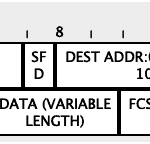
The VLAN tag
To support VLANs, a special “tag” needs to be applied to packets so that network devices can know how to forward those packets correctly.
While different vendors have their own proprietary method for creating this tag (e.g. the now deprecated Cisco ISL protocol), a standard supported by most networking devices for supporting VLANs on Ethernet networks is the IEEE 802.1Q standard.
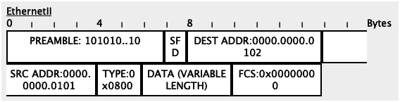
802.1Q adds a 32-bit field (4 bytes) inside an Ethernet frame.
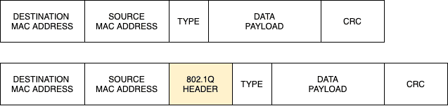
The first 16 bits in this field (TPID) are used to identify the frame as an 802.1Q tagged frame while 12 out of the remaining 16 bits are used to carry the VLAN ID.
The remaining 4 bits are mainly used for Quality of Service (QoS) operations.
12 bits used for the VLAN ID means that 4096 VLANs can theoretically be supported i.e. 2^12 = 4096.
However, all 0s (0x000 in hexadecimal) and all 1s (0xFFF in hexadecimal) are reserved bringing the total supported VLANs to 4094.
Note that network vendors may also implement their own VLAN ID restrictions.
How VLAN Works
Before VLANs, the decision a switch had to make was easy:
- If the switch receives a broadcast packet or a unicast packet for which it does not know the destination MAC address, it will flood that packet to all its other ports except the one it was received on
- If the switch receives a unicast packet and it knows the destination MAC address, it will forward that packet only to the port on which the destination device is connected
With VLANs, there are a couple of things to be considered:
- Is the packet destined for a device connected to the same switch or to a device on a different switch (in the same VLAN)?
- What should the switch do if it receives a packet without a VLAN tag i.e. untagged packet?
- What should the switch do if it receives a packet with a VLAN tag i.e. tagged packet?
To answer these questions, we will discuss the following concepts: Default VLAN, Untagged Port, Tagged Port, and Native VLAN.
Default VLAN
Most switches that support VLANs come pre-installed with a default VLAN. This means that all the ports on that switch will belong to the default VLAN by default (pun intended). This is the reason you can buy a new switch, connect multiple devices to this switch, assign these devices IP addresses, and they can immediately communicate with themselves. For most vendors, the default VLAN is VLAN 1.
The snapshot below shows all the ports on a new Cisco 2960 switch in the default VLAN 1:
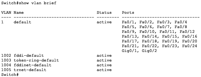
You will need to manually configure a port as part as another VLAN to remove it from the default VLAN.
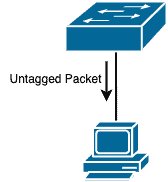
Untagged Packet/Port
Most end devices that connect to a switch do not care about or understand VLAN tagging.
They just want to be able to communicate on the network.
This includes devices like workstations, IP cameras, and even some servers.
When these devices send packets to the switch, they send plain Ethernet frames (i.e. untagged packets) and it is up to the switch to determine how to forward that packet.
Note: Many network interface cards can be configured to understand VLAN information and even tag packets with VLAN IDs but this is not enabled by default since it is not a common requirement. See this article for how to enable VLAN tagging on Windows.
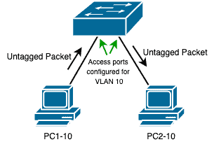
In most cases, the switch ports that connect to such end devices will be configured with a specific VLAN ID and that’s how the switch will determine how to forward the packet.
For example, if a switch receives an untagged packet from a device connected to its Fa0/1 port and that port is assigned to VLAN 10, then the switch will know that it needs to forward the packet to another device (or devices) in VLAN 10.
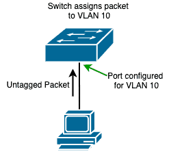
Note: If that port is in its default state, then it will belong to the default VLAN and untagged packets will be treated as belonging to that default VLAN.
These ports that connect to end devices are called “untagged ports” and can only be configured for a single VLAN.
Hint: Cisco calls this type of ports “access ports“.
Before the switch forwards packets out of an untagged port, it strips away any VLAN information from that packet since the receiving device won’t understand them anyway.
Note: Depending on the vendor, an untagged port that receives a tagged packet will drop that packet, except the VLAN tag matches the VLAN configured on that port.
Tagged Packet/Port
On the other hand, some devices understand and participate in VLAN tagging.
It means these devices tag the packets they send and can also understand when they received a tagged packet.
A switch is a typical example of such a device.
Since VLANs can span multiple switches, it means there needs to be a way for tagged packets to travel from one switch to another.
To do this, a single port on the same VLAN can be used on both the switches to carry traffic for that VLAN:
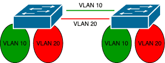
However, this becomes impractical and defeats the purpose of VLANs when you have multiple VLANs.
A better alternative will be a single port that can carry packets from multiple VLANs.
In this case, the switch will need to tag packets correctly for their correct VLANs as they exit the port and the receiving device (e.g. another switch) on the other end must understand this tagging and forward these packets to the correct VLANs:
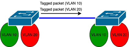
These ports are known as “tagged ports” because the switch applies tags to the packets sent from such ports.
Depending on the vendor, tagged ports are able to carry traffic for all VLANs by default but a filter can be applied on such ports to limit the allowed VLANs.
Hint: Cisco calls this type of ports “trunk ports“.
Native VLAN
In the subsections above, we have considered the following scenarios:
- Untagged packet received on an untagged port: forward based on VLAN configured on the port
- Tagged packet received on an untagged port: drop packet except the tag is the same as the VLAN configured on the port
- Tagged packet received on a tagged port: forward based on the VLAN tag in the packet
There is the last scenario we have not considered: what should a tagged port do if it receives an untagged packet?
Since that port can carry multiple VLANs and is not assigned to a single VLAN, what VLAN tag should it apply to that untagged packet?
This is where the Native VLAN comes in.
The Native VLAN is the VLAN associated with all untagged packets on a tagged/trunk port.
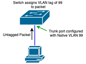
Depending on the vendor, the Native VLAN is usually the same as the default VLAN on the switch e.g. VLAN 1.
This can be changed on a per-port basis.
Note: On Cisco switches, any packet sent from a trunk port that matches the Native VLAN ID will be sent untagged. This is why, among other reasons, it is recommended that native VLANs match on both sides of a trunk.
VLAN Tagging Scenarios
To deepen our understanding of these different terms, let us look at a few scenarios.
We will use the following lab built using Cisco Packet Tracer:
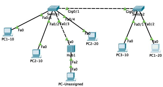
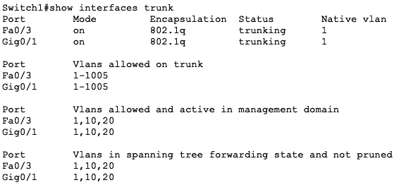
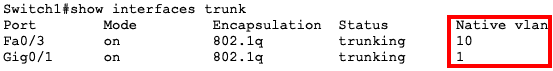
The port configuration on the switches is as follows:
| Switch | Port | Type | VLAN |
| Switch1 | Fa0/1 | Access | 10 |
| Fa0/2 | Access | 10 | |
| Fa0/3 | Trunk | ALL | |
| Fa0/4 | Access | 20 | |
| Gi0/1 | Trunk | ALL | |
| Switch2 | Fa0/1 | Access | 10 |
| Fa0/2 | Access | 20 | |
| Gi0/1 | Trunk | ALL |
The IP and MAC addresses on the PCs are as follows:
| PC | MAC Address | IP Address |
| PC1-10 | 0000.0000.0101 | 192.168.10.1 |
| PC2-10 | 0000.0000.0102 | 192.168.10.2 |
| PC3-10 | 0000.0000.0103 | 192.168.10.3 |
| PC1-20 | 0000.0000.0201 | 192.168.20.1 |
| PC2-20 | 0000.0000.0202 | 192.168.20.2 |
| PC-Unassigned | 0000.0000.0FF1 | NIL |
There is communication between all the devices in the same VLAN and ping has been used to test this connectivity.
This means that the MAC address tables of the switches have already been populated with the correct port to MAC address mapping.
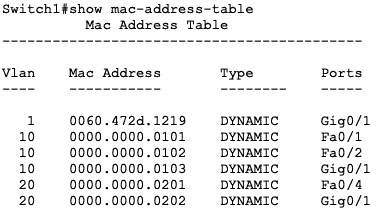
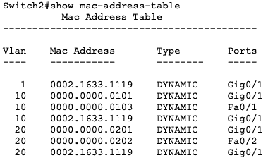
Note: There is currently no communication between devices in VLAN 10 and VLAN 20. To enable interVLAN communication, a layer 3 device is required.
Scenario #1: Untagged Packet Received On/Sent Out from Untagged port
In this scenario, PC1-10 will ping PC2-10. The configuration on the switch ports they are connected to is as follows:
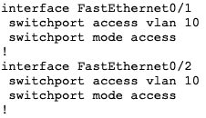
Since both ports (Fa0/1 and Fa0/2 on Switch1) are untagged ports, there will be no VLAN tagging on those ports.
The switch will just use the VLAN configured on the port to forward the packets correctly.
We can see this by switching to “Simulation” mode in Packet Tracer.
The packet as received on Fa0/1 (ingress) is shown below:
The packet as sent out from Fa0/2 (egress) is as shown below:
Notice that there is no VLAN information in the Ethernet frames of both ingress and egress packets.
Scenario #2: Tagged Packet Sent From/Received on Tagged port
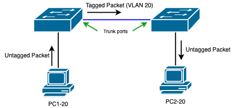
In this scenario, PC1-20 will ping PC2-20. Since these devices are on the same VLAN, communication will be permitted.
However, since they are on different switches, the packets will need to be tagged on the trunk link between Switch1 and Switch2.
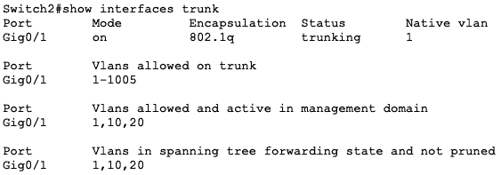
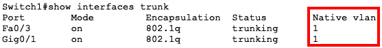
The images below show the trunking operation on both switches.
Notice that Gi0/1 on both switches are trunk ports:
Let’s look at the packets as they flow from port to port.
First, PC1-20 will send an untagged packet to Fa0/4 on Switch1:
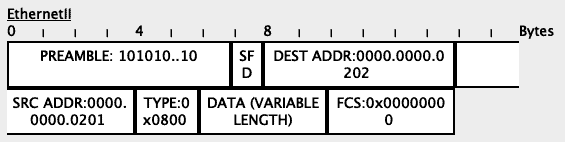
Based on its MAC address table, the switch will determine that the packet needs to flow out through the Gi0/1 interface.
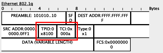
Since this is a trunk port, the switch will include the VLAN tag of 20 (hexadecimal 0x0014) into the frame:
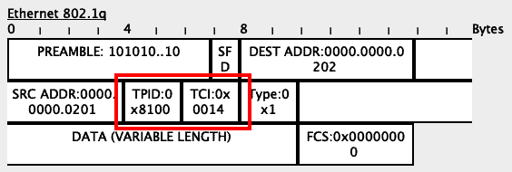
When Switch2 receives this packet, it will see the VLAN tag in the packet:
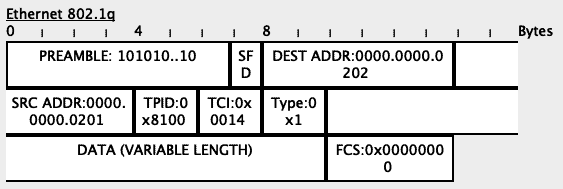
Based on its MAC address table, Switch2 will determine that the packet needs to go out through its Fa0/2 interface.
Since Fa0/2 is an untagged/access port, the switch will strip all VLAN information from the frame before sending it along:

Scenario #3: Untagged packet received on Tagged port
In this scenario, we will simulate an UnTagged packet being received on a tagged port.
To do this, we will send a DHCP packet from PC-Unassigned through the Hub to the Fa0/3 port on Switch1.
This port is configured as a trunk port on Switch1:
![]()
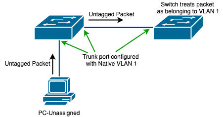
PC-Unassigned will send an untagged packet to Switch1 (through the Hub):
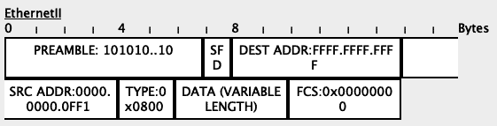
Since this is an untagged packet received on a tagged port, Switch1 will associate that packet with the Native VLAN on that port.
In our case, the Native VLAN is VLAN 1.
This brings us to two options:
- The native VLAN on the ingress port is the same as the native VLAN on the egress port
- The native VLAN on the ingress port is different from the native VLAN on the egress port
Let’s consider the first option:
Since the packet is a broadcast packet (destination address of FFFF.FFFF.FFFF), Switch1 will flood it to all ports in that VLAN (VLAN 1 in this case).
In our lab, the only other device in VLAN 1 is the trunk port to Switch2 so the packet will be sent out the Gi0/1 port towards Switch1.
However, since the tag on the packet (VLAN 1) is the same as the Native VLAN on the egress port (Gi0/1), the packet will be sent untagged:
When Switch2 receives the untagged packet, it will also apply its own configured native VLAN to that packet and forward it appropriately:

In our lab, there are no other devices on VLAN 1 so this packet will eventually be dropped.
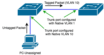
To see the second option, we will change the Native VLAN on the Fa0/3 port to another VLAN e.g. VLAN 10:
In this case, Switch1 will send the packet to all devices in VLAN 10, including over the trunk link to Switch2.
Since the tag on this packet is different from the Native VLAN, the packet will be sent with its tag on:
Scenario #4: Mismatched Native VLAN
Scenario #3 above presents a potential problem – if traffic that matches the Native VLAN is sent untagged, what if there is a mismatch in the native VLAN on the trunk link between two switches?
Let us see this with a theoretical scenario:
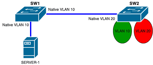
The switches are connected via trunk ports.
The server is also connected via a trunk port to SW1.
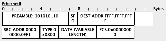
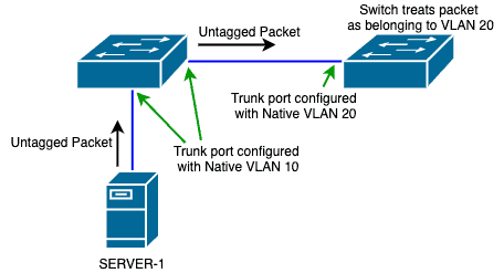
Now, imagine that SERVER-1 sends an untagged packet to SW1.
When SW1 receives this packet, it will apply a VLAN tag of “10” to that packet.
Now, assuming that this packet needs to be sent to SW2, SW1 will strip the VLAN tag away and send the packet untagged to SW2 since the tag on the packet matches the Native VLAN on the egress port.
When SW2 receives this untagged packet, it will apply a VLAN tag of “20” to that packet because that is the Native VLAN configured on that ingress port.
Therefore, SW2 will forward that packet to VLAN 20 on its own end.
This means that traffic that started on VLAN 10 ended up on VLAN 20.
However, the theory is different from what will happen on most networks today that have VLAN-aware Spanning Tree Protocol (STP) running.
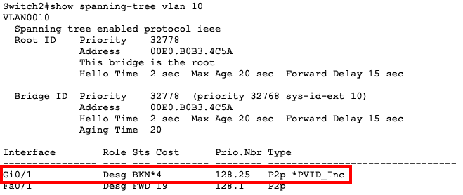
For example, on Cisco switches with CDP enabled, CDP will detect that the native VLANs are mismatched:
![]()
Secondly, STP will block that port on the affected VLANs:
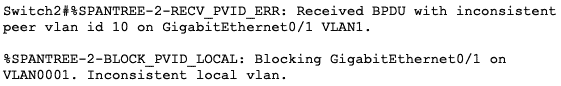
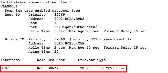
What it means is that traffic will not flow on that link for the affected VLANs.
All other VLANs will still be fine.
You can read more about this in this document.
This scenario has shown us a couple of things, especially from a Layer 2 security perspective:
- As much as possible, keep the Native VLAN on both sides of a trunk the same to avoid unforeseen issues
- For security reasons, change the Native VLAN on trunk ports from the default VLAN to a VLAN that is unused by other devices. Even if untagged packets get on that trunk port, the traffic will end up in an unused VLAN.
- Statically configure ports as either access or trunk ports and don’t allow for trunk negotiation. This will prevent an attacker from negotiating a trunk link and sending harmful packets.
- Any unused port should be placed in an unused VLAN and put in shutdown mode.
VLAN Tagging and Network Security
Network administrators can construct logical network segments, improve security, maximize network resources, and more using the powerful networking technique known as VLAN tagging. While implementing a VLAN using VLAN tagging requires more work, it gives access to a considerably wider range of network advantages, such as:
- More Security Features By including identifier tags into the user authentication process, users can be automatically and dynamically directed to the appropriate VLAN, which by nature protects them from receiving any broadcast from other networks. In addition, IT can utilize a VLAN provider to set up several firewalls and other security programs according to the importance of the data carried through each tagged VLAN.
- Resource optimization Businesses can more effectively distribute resources by establishing VLANs in accordance with network requirements. For instance, they can allocate more bandwidth to apps that are essential and less to those that are not, ensuring that crucial tasks have the required network resources.
- Less Congestion The linear design of Untagged VLANs places restrictions on their use. Untagged VLANs nevertheless hamper network performance, while producing better traffic management than LANs.
- Broadcast Control All devices in a broadcast domain get broadcast traffic in traditional Ethernet networks, which adds needless congestion to the network. In simple terms, VLANs reduce network congestion and enhance overall network performance by restricting broadcast traffic scope to devices inside the same VLAN.
- Less Expenses To move data where it needs to go, untagged VLANs require more switches. However, tagged VLANs already have the direction of the traffic configured, which increases their efficiency and eliminates the need for expensive hardware.
- Compliance and Regulatory Standards By separating sensitive data from the data that is less important, VLAN tagging can assist enterprises in complying with security and regulatory standards. Sensitive data is protected from unauthorized users or devices thanks to this segregation.
- Troubleshooting and Updates IT teams have access to check all VLAN tags, which makes it simpler for them to identify the source of any problems. Additionally, VLAN tags are easily updated at any moment, allowing IT to make quick changes without significantly affecting the working hours of employees. In addition, IT teams can quickly establish and add more tagged VLANs to the overall network if the business is expanding (physically or virtually).
Conclusion
In this article, we have looked at VLANs in detail with a focus on the type of ports involved in VLAN tagging.
To summarize this article:
- VLANs allow us to segment layer 2 networks
- To achieve VLANs, a tag is applied to frames to identify what VLAN a particular packet belongs to
- The ports on most network switches belong to a default VLAN e.g. VLAN 1
- 1Q is the standard used for VLAN encapsulation on Ethernet frames
- Packets can either be untagged (no VLAN tag) or tagged (VLAN tag)
- Ports on a switch can either be untagged (does not tag packets; belongs to a single VLAN) or tagged (tags packets; can carry multiple VLANs)
- When an untagged port receives an untagged packet, the switch will forward the packet based on the VLAN configured on that port
- When an untagged port receives a tagged packet, the switch will drop the packet if the tag on the packet is not the same as the VLAN configured on that port. This behavior is vendor-specific
- A tagged port can send both untagged and tagged packets
- When a tagged port receives an untagged packet, it applies its native VLAN to that packet
- Packets that match the native VLAN configured on a tagged port are sent out untagged
- Mismatched Native VLANs can cause unforeseen problems in a network
Tagged, UnTagged and Native VLANS FAQs
What is the difference between tagged and untagged VLANs?
Tagged VLANs use VLAN tagging to add an additional header, called a VLAN tag, to the packet, which contains the VLAN ID. This allows for multiple VLANs to traverse the same link.
What are some everyday use cases for tagging VLANs?
A few use-case examples for VLAN tagging include:
- Quality of Service (QoS) - Tagging VLANs allows for the prioritization of different types of traffic, such as voice or video, by assigning them to different VLANs and applying different QoS policies to each.
- VLAN Routing - Tagging VLANs enables routing between different VLANs within the same network, providing a more efficient means of communication between devices in different VLANs.
- Security - Tagging VLANs allows for creating VLANs dedicated to specific security purposes, such as guest networks or DMZs.
Related Post: Cisco Commands Cheat Sheet